
LC to LC UPC Simplex OS2 Single Mode Fiber Optic Test Cable with 10dB Attenuator
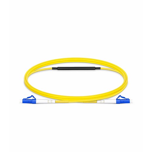
Engineering teams can use the documented values below to compare the product with the intended channel and as-built requirements. LC to LC UPC Simplex OS2 Single Mode Fiber Optic Test Cable with 10dB Attenuator combines a precision fixed attenuator with a test-grade patch cord in one item. It exists for one recurring job: proving that a long-reach transceiver works at its specified receive level without deploying the full fiber channel. Plug it between this loopback and the test set, and the 10 dB element reproduces the optical path loss the optics were designed to tolerate.
Product Highlights
- Standard Fixed Attenuation Value of 10dB
- Applied for CWDM, DWDM, Test Equipment, CATV Systems, Point to Point Systems, etc.
- Attenuating Material-ion Doped Fiber
- 1310/1550nm Wavelength Singlemode Attenuators
- Precision Polishing for Reduced Back Reflection
Specifications
| Attenuation | 10dB |
|---|---|
| Return Loss | ≥45dB |
| Operating Temperature Range | -25 to 70°C (-13 to 158°F) |
| Storage Temperature Range | -40 to 85°C (-40 to 185°F) |
| Application(1) | Specification(1) |
| Attenuation:15dB | Just what I needed, worked great. |
Why links need attenuation at all
Optical links are engineered with a power budget: the transmitter launches, the fiber and connectors consume, and the receiver expects what remains inside a defined window. Short routes, dense wavelength plans and high-power transmitters may all deliver too much light, and an overloaded receiver distorts exactly like an overloaded amplifier - errors appear on an optical path that tests perfectly on loss alone. A fixed attenuator brings the received power back inside the window, and the optical path behaves as designed.
Ion-doped fiber as the attenuating element
The cleanest way to attenuate light is to absorb it inside the fiber itself. Ion-doped fiber attenuators do exactly that: a short section of doped glass absorbs a calibrated fraction of the optical power and converts it to negligible heat. Because the attenuation happens inside the core, the light that emerges keeps its mode profile and the device adds virtually no reflectance. The alternatives - air gaps, offsets and misaligned ferrules - all trade loss against reflections and modal noise, which is why precision attenuators abandoned them. Project teams can retain this information with the as-built documentation for later review.
Attenuator test cables for transceiver qualification
Long-reach transceivers are specified to work over tens of kilometers of fiber; the test bench has none. The attenuator test cable reproduces the channel loss in a one-meter item: a calibrated 10 dB element sits inline between two LC connectors, and this loopback under test sees exactly the receive level it would see at the end of the designed optical path. Loop the transmitter back through the relevant cable, and the full operating range is verified before this loopback ever leaves the lab.
Attenuation in testing and calibration
Beyond live links, attenuators are the reference instruments of the fiber lab. Receiver sensitivity is measured by adding loss until errors appear; power meters are calibrated against known attenuation data; a new transceiver type is qualified across its receive range before implementation. Fixed attenuators provide the stable reference points, and variable attenuators sweep the range between them. The two must hold their rated specification over wavelength and temperature, which is what separates a calibrated device from a decorative one.
Handling and cleaning attenuators
An attenuator is a connector with optics inside, and connector rules apply: keep the caps on until the moment of mating, clean each end face before insertion, and never mate a contaminated ferrule into the device - the dirt transfers to the attenuator end face and the next connector that touches it. Store spare units capped and bagged, and record which optical path every fitted unit serves so replacement orders match the original specification.
Selecting the right attenuator
Four decisions define the order: the attenuation specification must be compatible with the optical path calculation, the relevant connector product line must be compatible with the port or the patch leads, the polish grade must be compatible with the plant, and the body style - plug or inline - must suit the deployment. Fixed data cover permanent installations; the variable instruments cover testing; the test cable covers transceiver qualification. Getting all four right at order time is what turns a small component into a dependable part of the optical path.
Quality Control and Testing
Each attenuator is optically verified before packing: the attenuation specification is measured at the operating wavelengths and checked against its rated tolerance, return loss is verified to its polish grade, and the relevant connector end faces are inspected for scratches and contamination. Units ship capped and bagged.
Ordering and Factory Support
Refer to this attenuator by attenuation specification, connector product line, polish grade and body style when requisitioning a quotation. For data or configurations outside the listed options - non-standard dB figures, mixed connector pairings or project packing - send the requirement with the enquiry and the factory will cross-check the manufacturable specification. Project orders can include documentation and labeling requirements alongside the technical configuration.
Purchase with confidence
Get a quick quote
Please write to sales@huihongfiber.com, we will reply as soon as possible.
Fiber cable assemblies
Transceivers and cables
Testers and tools
| Fiber Optic Test Equipment |
| Fiber Optic Tool Kits |
Huihong TechnologiesAdd:6F,1st Bldg,ZYT industrial park, Shiyan area,Shenzhen,ChinaEmail:info@huihongfiber.com Tel: 86.755.61230063 Specialized fiber optic products manufacturer. |
Fiber Optic Quick Guide |
News and ExhibitionsCompany news and exhibitions schedules for this year and next year. click here for details . |
Fiber Optic Applications
|
Customer Support
|


Copyright © 1998 - 2015.
China fiber optic manufacturer and china fiber optic cable supplier,fiber optic transceiver manufacturer.


