
LC UPC to LC UPC Duplex Flat Clip Uniboot OS2, 2.0mm, ofnr Fiber Patch Cable
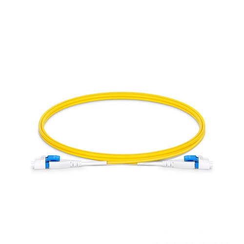
High-density designs should assess this item together with panel access, cable routing and the complete optical loss allowance. This OS2 fiber patch cable carries a LC UPC interface on one end and a LC UPC interface on the other, factory terminated on OS2 glass and optically tested as a full product. The uniboot structure places both fibers of the duplex channel inside a single round 2.0mm cord with one combined connector housing, halving this optical cable count in high-density panels and simplifying polarity management.
Product Highlights
- Uniboot Allows One Cable to Carry Two Fibers to Reduce Cable Congestion in High-Density Patch Fields
- G.657.A1 Bend Insensitive Fiber with 10mm Min. Bend Radius
- Flat Clip Design Provides Additional Space Between Connectors and Improves Airflow
- Reverse Polarity without Exposing the Fibers or Needing Any Tools
- Termination Is Tested to Ensure Network Performance
Specifications
| Fiber Count | 2 Fibers |
|---|---|
| Fiber Grade | G.657.A1 (Compatible with G.652.D) |
| Fiber Mode | OS2 9/125μm |
| Wavelength | 1310/1550nm |
| Flame Rating | Riser (OFNR) |
| Cable Outside Diameter (OD) | 2.0mm |
| Polarity | A (Tx) to B (Rx) |
| Tensile Strength | 60/100N (Long/Short Term) |
| Min. Bend Radius (Optical Fiber) | 10mm |
| Min. Bend Radius (Fiber Cable) | 10/5D (Dynamic/Static) |
| Insertion Loss | ≤0.2dB |
| Return Loss | ≥50dB |
| Attenuation at 1310nm | ≤0.4dB/km |
| Attenuation at 1550nm | ≤0.3dB/km |
| Operating Temperature | -10 to 70°C (14 to 158℉) |
| Storage Temperature | -20 to 70℃ (-4 to 158℉) |
Connector and polish choices in the single-mode plant
The OS2 interface on this jumper follows the polish discipline of the network it serves. Mixing polishes on a mated pair destroys the return loss and may damage the ferrules; consequently, the patch side must correspond to the patch panel side exactly. When the documentation is unclear, the boot color and this connector interface housing tell the truth: green for APC, blue or beige for UPC.
Bend tolerance in real cabinets
Patch fields are rarely kind to fiber. Leads pathway through tight managers, sharp tray corners and crowded vertical channels. The bend-insensitive glass in this terminated assembly tolerates a 10mm fiber bend radius; consequently, a hurried routing decision during a night upkeep window will not by itself turn into a measurable penalty on the channel.
Polarity without re-terminating
Uniboot connectors expose the polarity through the housing rather than the termination: the latches or clips let the installer swap the fiber positions without opening the cord. A polarity mistake discovered at turn-up becomes a two-minute correction instead of a replacement order. This check should form part of the rack-access and acceptance review.
Length Options
Standard cable lengths cover the common patching routes: 0.5m (1.6ft), 1m (3ft), 1.5m (5ft), 2m (7ft), 3m (10ft), 5m (16ft), 7m (23ft), 10m (33ft), with custom length obtainable beyond the list. Specifying the measured pathway length keeps the slack out of the manager and the strain off these optical interfaces.
Quality Control and Testing
Each completed assembly is terminated with precision zirconia ferrule connectors and optically tested before packing: insertion loss and return loss are verified on each cable, and end-face geometry is inspected for consistent physical contact. This optical cable ships with dust caps on both connectors and the test result obtainable on ask for.
Ordering and Factory Support
Refer to this arrangement by connector pair, fiber mode and length during the request for a quotation. For configurations outside the listed options, mixed connector families, jackets, marking or project packaging, send the requirement with the enquiry and the factory will review the build before manufacturing begins. Project orders can be reviewed for interface compatibility, packing details and delivery coordination.
Purchase with confidence
Get a quick quote
Please write to sales@huihongfiber.com, we will reply as soon as possible.
Fiber cable assemblies
Transceivers and cables
Testers and tools
| Fiber Optic Test Equipment |
| Fiber Optic Tool Kits |
Huihong TechnologiesAdd:6F,1st Bldg,ZYT industrial park, Shiyan area,Shenzhen,ChinaEmail:info@huihongfiber.com Tel: 86.755.61230063 Specialized fiber optic products manufacturer. |
Fiber Optic Quick Guide |
News and ExhibitionsCompany news and exhibitions schedules for this year and next year. click here for details . |
Fiber Optic Applications
|
Customer Support
|


Copyright © 1998 - 2015.
China fiber optic manufacturer and china fiber optic cable supplier,fiber optic transceiver manufacturer.


